


Importance of shed geometry on operational performance of Weaving machines
Purpose: To reduce end breaks during the running of weaving machines and improve productivity/ quality of cloth woven.
The effect of shed geometry has been studied on a loom under the combination of weaving conditions that give the best cover and least stress on loom and warp yarns determined.
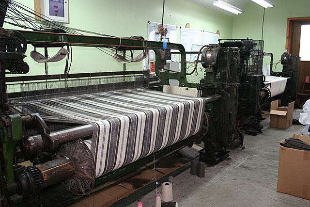
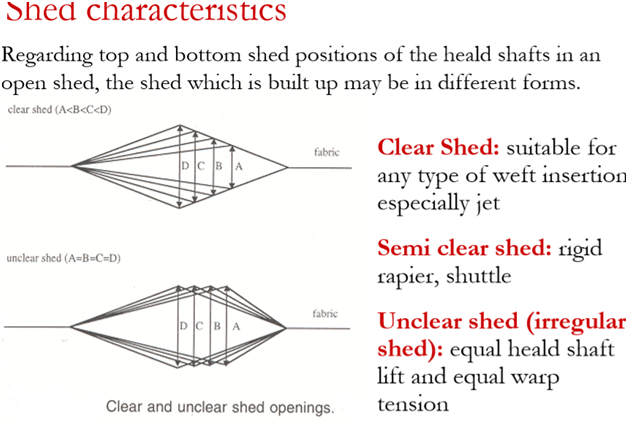
Shedding Mechanisms
All weaving machines control the warp yarns to create a shed. This can be accomplished with the following systems:
- Crank shedding
- Cam shedding or tappet shedding
- Dobby shedding
- Jacquard shedding
Crank, cam and dobby mechanisms control the harnesses which lift the shafts. Jacquard machines control the individual warp yarns. Each system is outlined below:
Crank Shedding
Crank shedding mechanisms are simple and relatively cheap to use. However, it can only be used for plain weave fabric constructions. In this system, the harnesses are controlled by the crankshaft of the weaving machine. For each crankshaft revolution, a wheel is rotated half a turn, which changes the harness position. This system is only used in air-jet and water jet machines where high speed is achieved.Cam Shedding
Cam shedding is also simple and inexpensive. A cam is a disk which has grooved or conjugated edges which correspond to the lifting plan. The lifting plan controls which harnesses are lifted. The disadvantage of cam shedding is that when the woven design has to be changed the cams have to be rearranged to suit the new design. Pattern design is also limited due to the number of harnesses the cams can control.Dobby Shedding
Dobby shedding is more complex than crank and cam systems. The main advantage of dobby looms is that more intricate designs can be produced. Older dobby looms were operated by wooden lags with pegs, which rotated around a roller above the loom. The pegs in the lags correspond to the lifting plan, which controls which harnesses are lifted. Punched paper or plastic pattern cards can also be used. Recently modern dobby looms are controlled via an electronic system. The disadvantage of dobby systems is that faults are more likely to occur due to their complexity.Jacquard Shedding
In jacquard weaving, a device called a ‘jacquard’ selects and lifts the warp yarns individually. This type of machine is used for larger more detailed patterns, where all or most of the yarns in a repeat, move independently. There are single or double lift machines which use either mechanical or electronic systems, using CAD to control the harness lifting and lowering. Modern jacquards are capable of handling over 1200 harness cords which control the lifting and lowering of the warp yarns.
Weft Insertion Methods
Modern automatic looms do not require a shuttle to carry the weft yarn across the shed. Instead, the weft yarn is inserted by either one of the following methods:
Rapier
A shuttleless weaving loom in which the filling yarn is carried through the shed of warp yarns by fingerlike carriers called rapiers. There are two types of rapiers.- A single long rapier that reaches across the loom’s width to carry the filling to the other side.
- Two small rapiers, one on each side. One rapier carries the filling yarn halfway through the shed, where it is met by the other rapier, which carries the filling the rest of the way across the loom. The insertion rate of picks can be up to 1000 m min-1.
Projectile
Projectile machines carry yarn through the shed using a small bullet shaped object known as a ‘projectile’. The yarn must be presented to the projectile in order for it to grip this. This process can occur in the following ways:- A single projectile is fired from each side of the machine alternately and requires a bilateral yarn supply.
- A yarn supply from one side of the machine is presented to the projectile. It carries the weft yarn across the machine and is then transported back to the other side by a conveyor chain. Several projectiles are in use at the same time to enable rapid pick insertion. Pick insertion rate can be up to 1300m min-1.
Air jet
In air-jet weaving machines, the filling yarn is inserted pneumatically. It is carried through the shed by compressed air flow supplied from the main nozzle and relay nozzles. This is the fastest type of weaving enabling pick insertion of 3000 m min-1.Waterjet
Water jet weaving is the same principle as air jet weaving, water is used instead of air and a similar speed is achieved. One disadvantage is that only hydrophobic yarns can be used.Multiphase
All of the above methods are classed as single-phase weaving, whereby the weft yarn is laid across the full width of the warp yarns and beat-up takes place. Multiphase weaving involves several phases of the weaving taking place at the same time so that several picks can be inserted simultaneously. The shedding mechanisms of the weaving affect this process:- Wave shed machines carry the yarn in either straight or circular paths. Parts of the warp are in different stages of the weaving cycle at any one moment. It is possible for a series of weft carriers to move along in successive sheds in the same plane.
- In parallel shed machines numerous sheds are formed simultaneously. Each shed extends across the full width of the warp and moves in the warp direction.
Factors to be considered before concluding shed setting geometry details which affect end breaks on weaving machine.
To create shed geometry machine settings, we need to have complete knowledge and understanding of
- Fabric cover factor: Cover factor is a number that indicates the extent to which the area of a fabric is covered by one set of threads. For any woven fabric, there are two cover factors: a warp cover factor and a weft cover factor.
Cloth Cover Factor
1. Warp cover factor = 2. Weft cover factor =
 3. Cloth cover factor =
 Total fabric cover factor= K1 +k2 – k1 k2/28. Where the k1= number of warp threads per inch/square root of warp count and K2 is a number of weft threads per inch/square root of weft count.
 - Yarn properties—material/ blends, elongation percentage, yarn imperfections, single thread strength etc.
Parameters Ring yarn Rotor Yarn Air-jet Friction Count range 1-100s Ne 2-40s Ne 20-60s Ne 1-40s Ne Production speed 2-25 mpm 100-200 mpm 150-200 mpm 150-200 mpm Strength 100% 75-85% 60-85% 60-75% Elongation at break 100% 100% U % D (maximum) C A (lowest) B Bulk 100% 100-125% 75-100% 100-140% Power consumption D (maximum) C A B Yarn Tension D (maximum) A B C - Yarn winding/warping —winding details/ end breakage studies
- Sizing ingredients applied on yarn: Textile warp sizing, also known as tape sizing, of the Warp yarns, are subjected during weaving to several types of actions i.e. cyclic strain, flexing, abrasion at various loom parts and inter yarn friction. breakage of the yarn and thus production stops on the weaving machine. With sizing, the strength — abrasion resistance — of the yarn will improve and the hairiness of yarn will decrease.
The degree of improvement of strength depends on adhesion force between fiber and size, size penetration as well as encapsulation of yarn. Different types of water-soluble polymers called textile sizing agents/chemicals such as modified starch, polyvinyl alcohol (PVA), carboxymethyl cellulose (CMC), acrylates are used to protect the yarn. Also, the wax is added to reduce the abrasiveness of the warp yarns. The type of yarn material, the thickness of the yarn, ends per inch, type of weaving machinery will determine the sizing recipe.
The Following procedure to be followed before appropriate settings are established
This procedure needs a lot of weaving skill and experience of the technical team who conducts this survey.
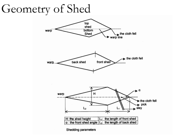


Effect of Shed Timing and Backrest Position
The early shedding coupled with the raised position of the backrest results in higher pick density in the woven fabric. The figure shows the normal and raised position of the backrest. When the backrest is at a normal position, the top and bottom sheds are symmetrical with respect to the Warp line when the shed is leveled. In this case, the length of two shed lines is equal which signifies that the tension in both the sheds (top and bottom) is equal. However, when the backrest is raised from its normal position, the length of shed lines become unequal. This becomes clearly visible from the fact that the length of the top shed line is smaller than the bottom shed line. Thus, the tension in the top shed line will be lower than that of bottom shed line.


Effect of changing backrest height For analyzing the effect of backrest position some data have been collected from different backrest height but same in backrest position, dropper position, dropper height etc. The data is summarized as follow: – Here (-)ve sign indicates the downward position and (+) ve sign indicates the upward position of the backrest
Effect of backrest height on warp tension


But when the backrest is up warded then the effect of drop wire weight will be high so more tension will be needed to straighten the warp thread
Effect of Changing Backrest Roller Backrest position creates very interesting and peculiar effect on warp tension, it is a surprising thing that only backrest position does not create any impact on warp tension but jointly with dropper position from backrest it affects the warp tension at a great scale.
The effect of Backrest position is influenced by the position of the dropper line. When the dropper line keeps its position constant (i,e both the backrest and dropper line is moved) then the backward position of the backrest roller will reduce the required tension. The reason behind this is, once the backrest is moved backward keeping the dropper position constant then the dropper depth increases which ultimately bring the dropper line near to the backrest in comparison with the dropper depth hence the impact of dropper weight will little as a result low tension will be required.
Conclusion The effect of backrest roller on warp tension and fabric quality cannot be ignored in anyways. From this study, it is known that different warp tension is observed due to different settings of backrest and dropper. The reason behind this behavior is different. Although modern loom has offered accurate tension by electronic means it is needed to readjust the tension when any settings mentioned in this paper is changed. This study let us know about the amount of tension readjustment while changing any settings related to the backrest. Improper tension is a major cause of faults like the starting mark. It is often seen in the factory that the starting mark appears in the loom frequently especially after running some days. For amending the starting mark, it is needed to readjust tension. If the starting mark is caused due to high tension then the tension should be minimized either by lowering the backrest or backward the drop wire. However, investigating the effect of tension on starting marks need higher level research using high technology like digital image processing technique.


Conclusions
Shed timing and shed geometry /unbalancing/yarn tension have an effect on the operational performance of the cloth-making process and consequently the fabric cover. There is a combination of loom settings related to the cloth shed geometry that can lead to a high performance on production efficiency and produce high-quality fabrics and also the best fabric cover can be obtained at ‘highest’ level of shed unbalance and ‘normal’ shed timing. There are certain interactions between the cloth making processes and the loom settings. Both the best cover and minimum BUF are obtainable at a high level of shed unbalance and ‘normal’ shed timing. However, this ideal setting may vary slightly for different looms, especially for high-speed modern looms in which the beat-up process occurs in a smaller fraction of loom cycle than on shuttle looms.
The effect of shed geometry has been studied on a loom under the combination of weaving conditions that give the best cover and least stress on loom and warp yarns determined. It is observed that the shed unbalancing shows improvement in the fabric cover. Shed timing, on the other hand, shows variable responses with the so-called ‘normal’ shed timing, resulting in a fabric of lowest reediness and highest pick density. The compromised setting for best fabric cover and least stress on the loom was observed at the high level of shed unbalancing and normal shed timing. All these factors are vital and critical to reducing end breaks on weaving machines and needs skill, knowledge and technical understanding of weaving operations.


